|
Impala/Monte Carlo DIC Installation |
Introduction
The Driver Information Center (DIC) a.k.a.
Overhead Console is available on both the 00-05 Impala as well as the 00-05
Monte Carlo. The DICs from the Impala and Monte Carlo are
interchangeable. There are two versions of the DIC available, one for
vehicles equipped with the power sunroof option (RPO CF5) and one for vehicles
without the sunroof option. The DIC features include an integrated
compass, external temperature display, Homelink transmitter, Average/Instantaneous Fuel
Economy, as well as other Trip Computer information.
Models/Parts
Below is a table of the
similarities/differences between the two consoles:
DIC Feature/Option Table
|
Feature/Option |
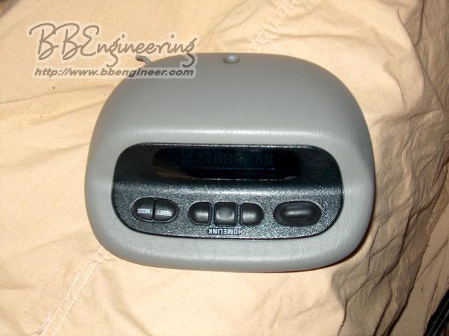
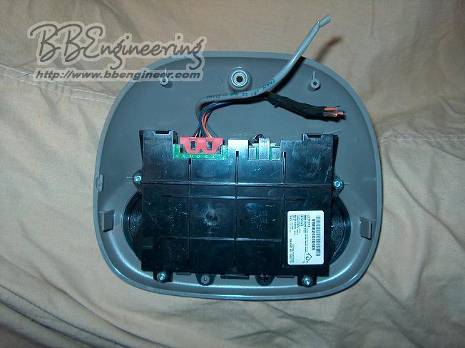
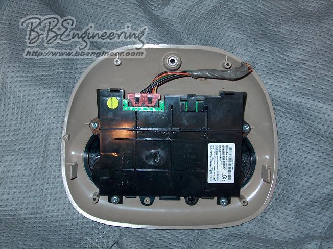
w/ Power Sunroof Option RPO U68 - DIC RPO UG1- Homelink RPO CF5 - Power Sunroof Click Image to Enlarge |
w/o Power Sunroof Option RPO U68 - DIC RPO UG1- Homelink
Click Image to Enlarge |
|
Bracket |
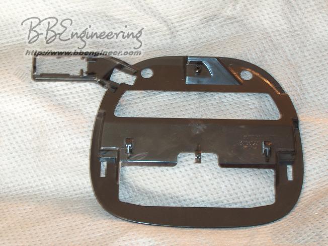
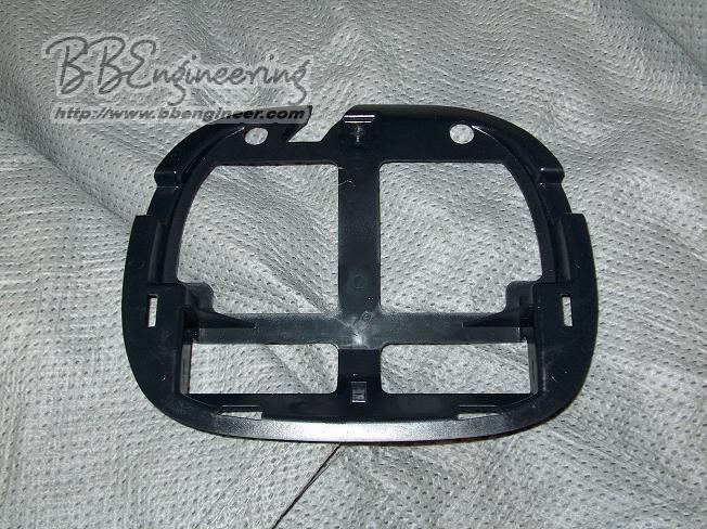
Mounting Bracket Click Image to Enlarge Bracket: GM Part # 10343287 ( $33.19 List ) |
Mounting Bracket Click Image to Enlarge Bracket: GM Part # 10447494 ( $30.56 List ) |
|
Homelink |
n |
n |
|
Ambient Temperature |
n |
n |
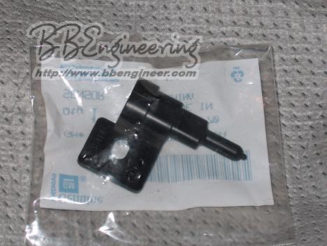
| Ambient Temperature Sensor |
Click Image to Enlarge Sensor: GM Part # 10248414 ( $12.40 List ) |
|
|
Compass |
n External Module (attached to bracket) NOTE: Available as part of DIC only |
n Internal Module
|
|
Trip Computer |
n |
n |
|
Integrated Sunroof Switch |
n |
r |
|
Driver Info Center
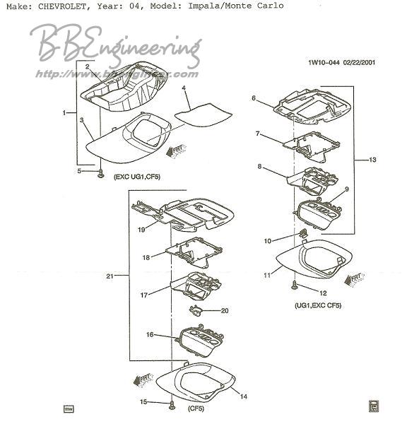
Disassembled View
Click Image to Enlarge |
Part Designator |
Description |
|
Overhead Console Storage |
||
| 1 | Overhead Console Storage (complete unit) | |
| 2 | Overhead Console Storage Bracket | |
| 3 | Overhead Console Storage Housing | |
| 4 | Overhead Console Storage Mat | |
| 5 | Overhead Console Storage Housing Screw | |
|
DIC (w/o Sunroof) |
||
| 6 | Overhead DIC (non-Sunroof) Bracket | |
| 7 | Overhead DIC (non-Sunroof) Module Cover | |
| 8 | Overhead DIC (non-Sunroof) Module | |
| 9 | Overhead DIC (non-Sunroof) Module Face | |
| 10 | Overhead DIC (non-Sunroof) Fastener | |
| 11 | Overhead DIC (non-Sunroof) Housing | |
| 12 | Overhead DIC (non-Sunroof) Housing Screw | |
| 13 | Overhead DIC (non-Sunroof) (complete unit w/o housing) | |
|
DIC (w/ Sunroof) |
||
| 14 | Overhead DIC (w/ Sunroof) Housing | |
| 15 | Overhead DIC (w/ Sunroof) Housing Screw | |
| 16 | Overhead DIC (w/ Sunroof) Module Face | |
| 17 | Overhead DIC (w/ Sunroof) Module | |
| 18 | Overhead DIC (w/ Sunroof) Module Cover | |
| 19 | Overhead DIC (w/ Sunroof) Bracket (w/ compass module) | |
| 20 | Overhead DIC (w/ Sunroof) Sunroof Switch | |
| 21 | Overhead DIC (Sunroof) (complete unit w/o housing) | |
Factory Wiring
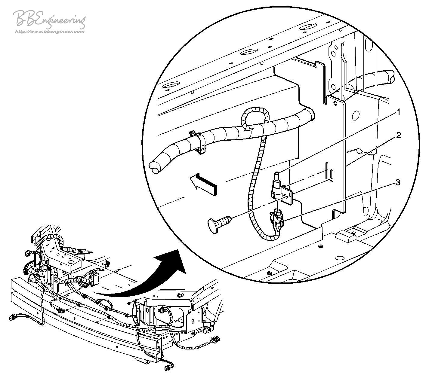
The DIC is not pre-wired in the roof harness if the DIC option was not ordered from the factory. The ambient temperature sensor is pre-wired behind the grill, in front of the radiator on all vehicles. The circuits needed for the DIC are available in harness that mates with the roof harness in the right C-Pillar (See diagrams below). These circuits present at the roof harness connector are the ambient temperature sensor, the Class-2 Data Bus, the sunroof control signals, and power/ground.
NOTE: It appears that the 9C1/9C3 Police Package does not bring the DIC wires up to the roof harness connector because the DIC is not an option on the Police Package Vehicles.
Below are the connector, schematic, and harness routing diagrams:
|
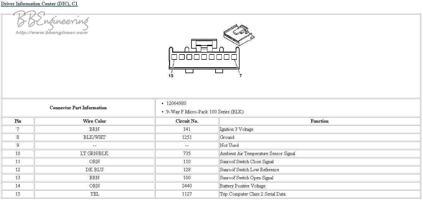
DIC Connector Pin Assignments (Located on DIC module in headliner ) |
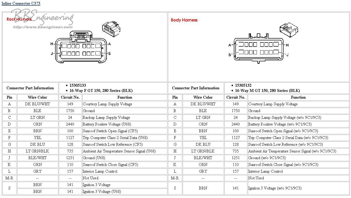
Roof/Body Harness Connector Pin Assignments ( Located in right side C-Pillar/Package Shelf) |
|
Click Image to Enlarge |
Click Image to Enlarge |
|
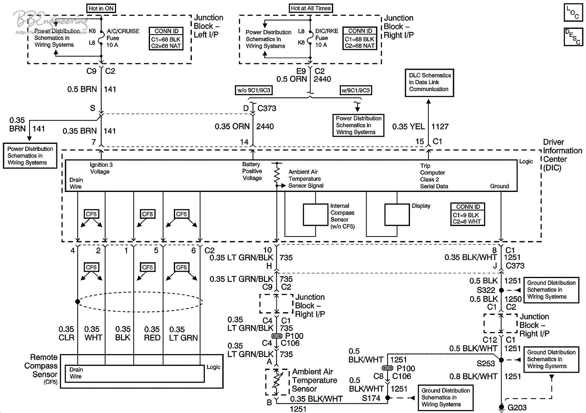
DIC Schematic Click Image to Enlarge |
|
|
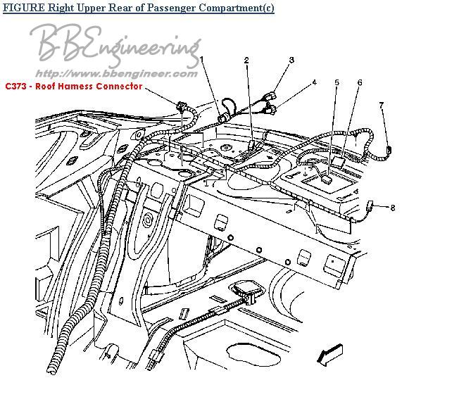
Roof/Body Harness Routing
( Located in right side C-Pillar/Package Shelf) Click Image to Enlarge |
Ambient Temperature Sensor Harness Routing ( Located behind right side of grill) Click Image to Enlarge |
Wiring The DIC
In order to actually get the DIC to work, it is necessary to get the appropriate signals, power, and ground connected to the module. There are a few ways to do this, but I will touch on only two of them here: Splicing into the factory wires and Using a Retrofit Harness
NOTE: It appears that the 9C1/9C3 Police Package does not bring the DIC wires up to the roof harness connector therefore splicing is the only option on the Police Package vehicles. Many of the circuits listed below are not available on the Police Package vehicles and new wiring must be added.
Splicing Connections
The benefit of splicing the connections is it is extremely inexpensive. All that is needed is a length of wire (8 conductors, 18-20 AWG), 8 Barrel Crimp Connectors (18-20 AWG), 8 T-Taps (18-20 AWG). It is possible to make all of the connections at the roof/body harness junctions, but since we are going to tap into the wires, some of them are available closer to the DIC location.
| DIC Pin | DIC Color | Circuit # | Function | Alternate Location |
| 7 | Brown | 143 | Ignition 3 | Rearview Mirror Harness - Headliner - (Brown) |
| 8 | Blk/White | 1251 | Ground | Rearview Mirror Harness - Headliner (Black) |
| 9 | -- | -- | -- | -- |
| 10 | Lt Grn/Blk | 735 | Ambient Temp Sensor | Roof/Body Connector (Lt Grn/Blk) |
| 11 | Orange | 110 | Sunroof Close | Sunroof Harness - Headliner (Orange) |
| 12 | Dk Blue | 128 | Sunroof Low Ref | Sunroof Harness - Headliner (Dk Blue) |
| 13 | Brown | 100 | Sunroof Open | Sunroof Harness - Headliner (Brown) |
| 14 | Orange | 2440 | Battery | Fuse Box |
| 15 | Yellow | 1127 | Class 2 Serial Data | Class 2 Data Splice Pack - Left Dash (Yellow) |
Be careful when tapping into the Class 2 Serial Data Bus because this is the same bus used to pass messages between computers (PCM, BCM, etc) and can screw up your electrical system completely if not done correctly
Custom Retrofit Harness
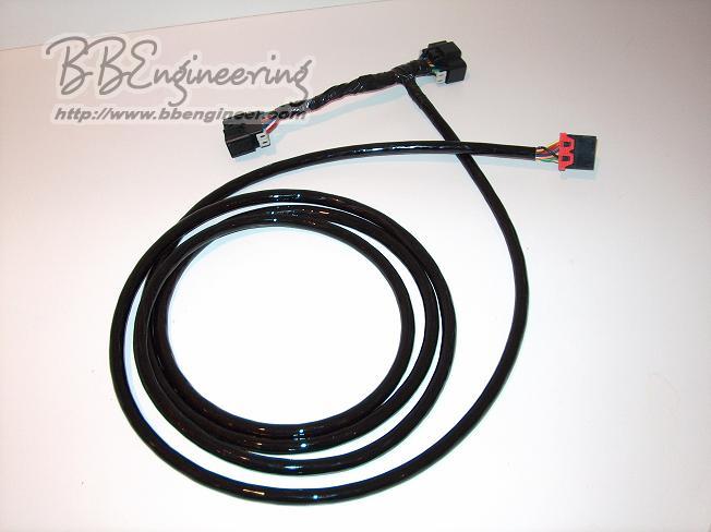
To make installation cleaner, I built a custom "T" harness that connects inline at the roof/body harness junction and runs up the C-pillar, along the edge of the headliner and to the DIC between the sun visors. The custom harness passes the non-DIC wires through from the body side to the roof side of the harness. The remaining DIC circuits (as well as circuits that are used for DIC and non-DIC functions) are routed up to the DIC.
The connections for this harness are as follows
| DIC Pin | DIC Retrofit Harness Color | Body Harness Color | Body/Roof Retrofit Harness Color | Roof/Body Pin | Roof Harness Color | Function |
| DK BLUE/WHT | BLUE | A | DK BLUE/WHT | Courtesy Lamps | ||
| BLACK | BLACK | B | BLACK | Ground | ||
| LT GRN | GREEN | C | LT GRN | Backup Lamps | ||
| 14 | ORANGE | ORN | D | ORN | Battery Supply | |
| 13 | BROWN | BROWN | E | BROWN | Sunroof Open Signal | |
| 15 | YELLOW | YELLOW | F | Class 2 Data Bus | ||
| 12 | BLUE | DK BLUE | G | DK BLUE | Sunroof Low Ref | |
| 10 | GREEN | LT GRN/BLK | H | Ambient Temp | ||
| 8 | BLACK | BLK/WHT | J | Ground | ||
| 11 | RED | ORN | K | ORN | Sunroof Close Signal | |
| GRY | WHITE | L | GRY | Interior Lamps | ||
| 7 | WHITE | BRN | BROWN | S | BRN | Ignition 3 |
Here is a picture of the harness:
Click Image to Enlarge
The short section at the top of the picture connects between the body and roof harness. The existing circuits are carried through while the circuits required by the DIC are split off to the DIC connector on the right (with the red pin lock).
The part numbers for the mating connectors can be found in the factory wiring section above.
NOTE: This Retrofit Harness will not work for the 9C1/9C3 Police Package because the DIC circuits are not present in the body/roof harness junction.
The harness can be routed from the bottom of the C-Pillar, up to the top of the C-Pillar, along the passenger edge of the headliner, and to the center of the roof where the DIC will be mounted. In order to make things easy, remove the passenger rear C-Pillar molding, the rear passenger grab handle/coat hook, and both sun-visor center clasps.
Note: The Retrofit Harness allows the DIC to be installed without cutting or splicing any connections, it is meant to be plug and play. It plugs inline with the roof/body harness connector located at the C-Pillar/Rear Deck junction. These harnesses are available for sale. For more information, send email to the address at the bottom of the page.
Mounting Details
The position of the DIC on the headliner is fairly critical (more so on the CF5 Sunroof equipped cars). The DIC is centered (left to right) in the headliner between the two sun visor retainer clips. The front edge sits approx 1/2" back from the windshield.
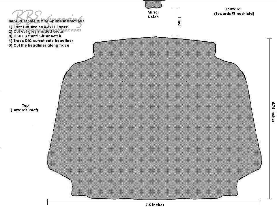
In order to mount the DIC, a hole must be cut in the headliner. Below is the template used for cutting the hole in the headliner. Simply print out a copy (full size, preferably on card stock), cut the center out the shaded areas and tape it to the headliner. Once it is in position, trace the cutout onto the headliner using a pencil.
Click Image to Enlarge
Before cutting the headliner, it important to move all of the existing harnesses out of the way. Pry them off the headliner (they are glued) and temporarily tape them to the underside of the roof. This will provide enough clearance so you don't cut the harness while making the mounting hole. To get enough clearance to work above the headliner, remove the sun visor retainer clips (and the sun visors as well if necessary). For sunroof equipped cars, you will have to remove the sunroof switch as well.
The hole in the headliner can be cut using a sharp utility knife. Make sure that you don't "break" or crease the headliner while cutting. You may have to trim the hole after you cut it. The utility knife works well for this also.
Once the hole is cut, position the mounting bracket above the headliner, make sure it is straight and in the correct position. Snap the front clips of the DIC into the bracket, then screw in the screw at the windshield.
Finishing Details
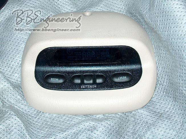
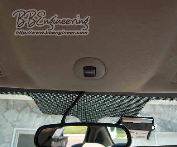
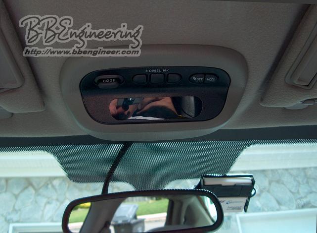
Here are the before and after pictures:
|
Before DIC Install (w/ Sunroof Switch) |
After DIC Install |
|
Click Image to Enlarge |
Click Image to Enlarge |
The color variation is due to the sun's position. The interior is medium grey.
Troubleshooting
Calibration Procedure (from the Service Manual )
Calibration
The compass is self-calibrating, eliminating the need to manually set the compass. Occasionally, the calibration process on a new vehicle may not be complete, causing the CAL symbol to illuminate. In order to correct this problem, drive the vehicle less than 8 km/h (5 mph) through 3 complete 360 degree turns. The CAL symbol will then turn OFF and the compass will function normally. If the compass appears erratic and the CAL symbol does not appear, you must manually put the compass into the calibration mode.
- Turn ON the ignition.
- Press the MODE button until the compass/temperature mode appears.
- Press and hold the RESET button on the overhead console for approximately 10 seconds, or until the display reads CAL.
- Release the RESET button and drive the vehicle less than 8 km/h (5 mph) through 3 complete 360 degree turns. The CAL symbol will turn off when the compass is calibrated, and the compass will function normally.
Variance
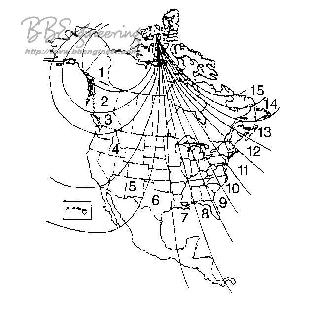
Variance is defined as the difference between magnetic north and geographic north. In some areas of the country, this difference is great enough to cause false compass readings. Set the variance for a particular location as follows:
- Determine the vehicle's location on the zone map. Note the zone number.
- Turn ON the ignition.
- Press the MODE button until the compass/temperature mode appears.
- Press and hold the RESET button on the overhead console for approximately 5 seconds. The last entered variance zone appears on the display.
- Press the MODE button until the correct zone number appears on the display.
- Press the RESET button in order to set the new variance zone and resume normal operation. The display will illuminate all segments briefly in order to acknowledge the change in the zone number.
Click Image to Enlarge

