|
Impala/Monte Carlo Cluster LED Upgrade |
Introduction
The 2000-2005 Impala and Monte Carlo gauge
clusters use a conventional incandescent light bulb for backlighting and some
of the indicators in the instrument cluster. These bulbs have a limited
life as any other convention light bulb does. LEDs offer a much longer
life span and consume far less current to produce the same amount of light.
The bulbs in the cluster are "not serviceable" according to GM, meaning they
are soldered to the circuit board rather than in socket and replaceable.
Follow along to learn how to convert your cluster to use LEDs for a modern
look.
WARNING: This modification takes some skill and experience soldering delicate electronics. I am not responsible for any damage that you do to your cluster, your car, or yourself as a result of this modification (or any other of my modifications).
If you are interested in doing this modification to your cluster, but don't feel comfortable doing it yourself, contact me at the address at the bottom for pricing.
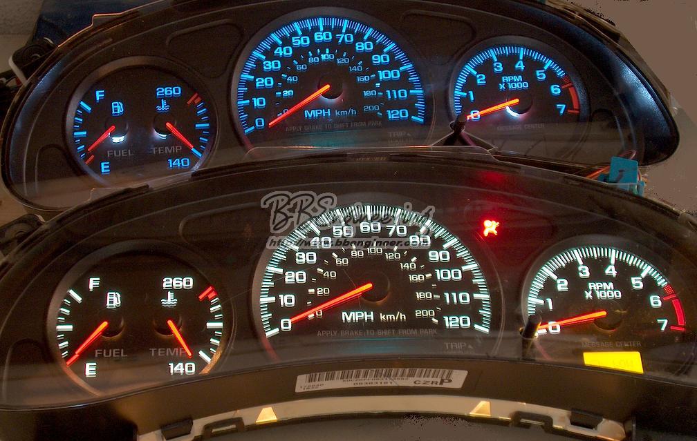
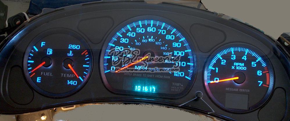
Here is a picture of the results (top cluster uses white LEDs, the bottom cluster is uses the factory bulbs)
Click On Image to Enlarge
Choosing LEDs and Resistors
A typical LED draws around 20ma (15ma - 30ma range) of current and has a voltage drop of around 2V (1.6V - 3.8V range). LEDs require a current limiting resistor (a regular carbon resistor in series with the LED) in order to run the LEDs off the 12-14VV supply of a car. In order to calculate the resistor value needed, use the following formula:
( 14.4V - V(forward)(volts) ) / I(forward) (amps) = R (ohms)
So for a typical LED:
( 14.4V - 2V ) / .02 = 620 Ohm (so use either 620 Ohm or 670 Ohm standard value resistor)
A 1/4 Watt resistor is a good choice (due to it's size) but a 1/2 Watt resistor will work just fine as well. Any tolerance value is sufficient for this application.
It is possible to get LEDs that have a built in resistor for 12V operation, but they aren't as many choices and they tend to be more expensive. The other problem is the 12V LEDs are meant to run on 12V and most cars produce upwards of 14V which will cause those LEDs to burn out prematurely. While the external LED solution isn't perfect, it is readily available and cost effective.
Another consideration when choosing an LED is the amount of light it produces (specified in mCd (milliCandela) ) as well as the viewing angle of the LED (measured in degrees from center) and the LED size. The LEDs that match the brightness of the factory bulbs should have 6000-8000 mCd and a viewing angle of 20 - 30 degrees. If you want a brighter cluster, use an LED with 10000-15000 mCd. I suggest using a 5mm LED as it's the same diameter as the cluster bulbs. You can use larger (ie: 10mm) but it will be a tighter fit.
On a side note, LEDs have a polarity to them, meaning they will only illuminate if the positive and negative legs are connected correctly. The longer leg on an LED is known as the Anode and is the positive leg. The shorter leg on an LED is known as the Cathode and is the negative leg.
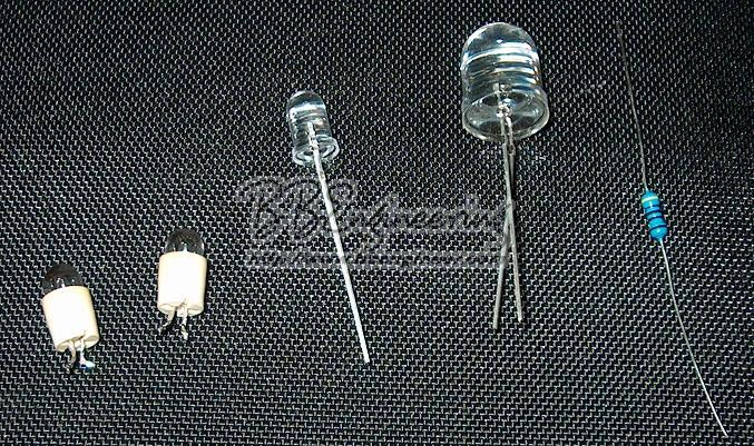
In this picture, the original cluster bulbs are on the left, then there is a 5mm white LED, followed by a 10mm white LED, and finally an 1/4 watt 470 Ohm resistor
Click On Image to Enlarge
Installation
Disassembling the Cluster:
WARNING: Before you remove the needles, you must take note of where the needles are so they can be put back in the correct place so the gauges are accurate. Refer to the section on gauge calibration before proceeding.
WARNING: Be careful with the circuit board, it is susceptible to static discharge. Make sure that you are grounded (wrist strap or similar) before handling the circuit board.
- First, remove the cluster from the dash. I am not going to go into dash removal here, there are plenty of resources on how to do this. Check the How-To links on http://www.impalahq.com for details
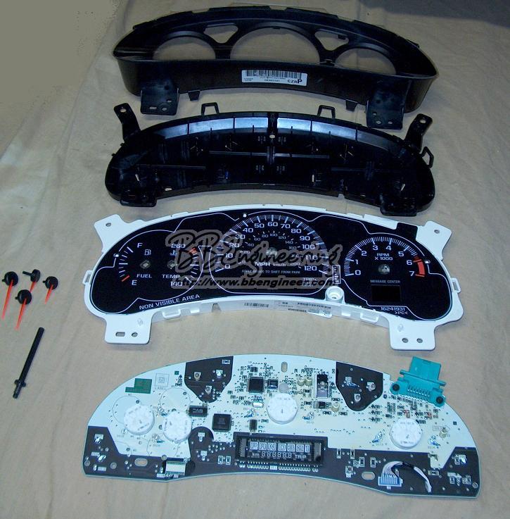
- Remove the front bezel (and trip button) by releasing the plastic snaps between the cluster body and the bezel
- Now that the bezel is removed, you must remove the needles. To remove the needles, use a small screw driver with some soft cloth wrapped around it (so you don't damage the overlays) to pry the center of the needle body up off the shaft. You may want to pry a little on one side, and then a little on the other side. You can also buy a tool to remove the needles, but it's really not necessary.
- Now, release the clips holding the back cover to the cluster body. Once these are released, you can remove the overlay carrier (white plastic piece) and the back cover to expose the circuit board.
Click On Image to Enlarge
Locating the bulbs:
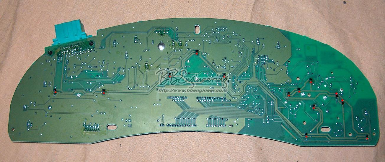
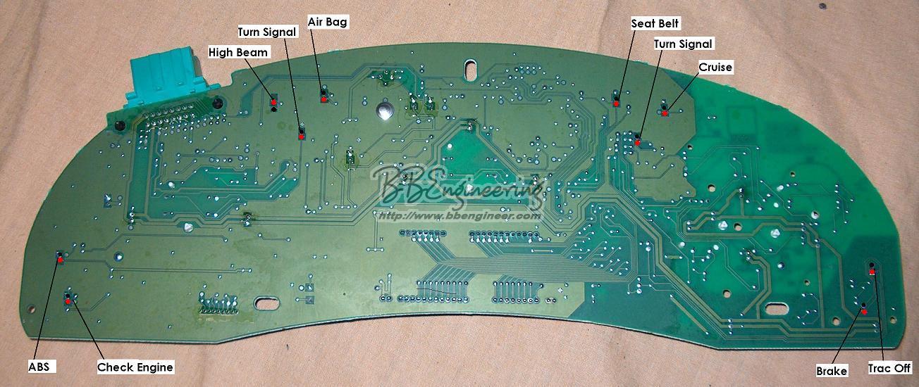
Below is a picture of the back of the cluster circuit board with the bulb connections highlighted. Not all of the bulbs will be present on all clusters. For instance, the SS cluster has more/different bulbs than the LS cluster and the base cluster. Some of the bulbs are already LEDs in newer clusters (mostly the indicator lights), so they do not need to be swapped.
The following picture highlights the locations of all of the backlighting bulbs. The positive side is marked with a red dot and the negative side is marked with a black dot.
Click On Image to Enlarge
The following picture highlights the locations of all of the indicator bulbs and LEDs. The positive side is marked with a red dot and the negative side is marked with a black dot.
Click On Image to Enlarge
Installing the LEDs:
WARNING: The circuit board is fairly delicate (and expensive). Do not apply too much heat when removing the bulbs or installing the LEDs or you will likely damage the board. If you are not comfortable working with electronics and soldering irons, please have this done by a professional. I am NOT responsible for any damage you do to your vehicle
In order to install the LEDs, you must first remove the bulbs. To remove the bulbs you will need to de-solder them from the circuit board. This will require either a de-soldering iron, or a soldering iron and some solder braid. Either one will work fine. Make sure you use a LOW wattage (25-30 Watts at most) soldering iron or you stand a good chance of destroying the circuit board.
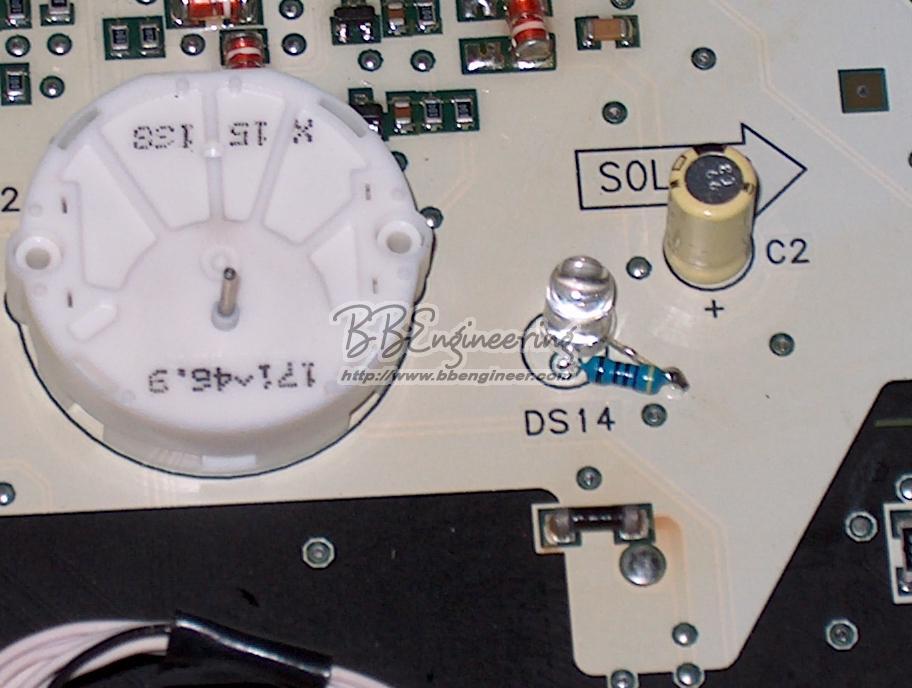
Once you have successfully removed all of the bulbs you want to swap, it's time to install the LEDs (and resistors if needed). Make sure you observe the polarity of the LEDs with regard to the circuit board. The negative LED lead should be installed in circuit board hole. The Resistor should be installed in the positive circuit board hole and the positive LED lead should be connected to the other side of the resistor. Make sure that you don't create a solder bridge between the holes on the back and that the resistor/LED junction does not touch any metallic pads or components on the front.
When soldering LEDs, be careful because they are heat sensitive (the resistors are not sensitive). Don't apply the soldering iron to the LED for more than a couple of seconds at a time. Allow the LED to cool in between soldering attempts
Here is a picture of an LED installed with an external resistor.
Click On Image to Enlarge
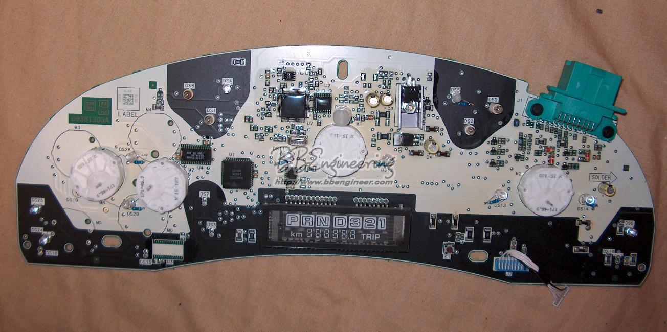
Here is a picture with all of the backlighting bulbs changed to LEDs. Notice the 10mm LED in the top/center of the picture. The face of it has been ground down and frosted to disperse the light more and prevent a pin-point of light from the LED.
Click On Image to Enlarge
Some of the indicators will have coloration from the overlays and some won't. For the the indicators that are not colored on the overlays (hold the overlay up to the light to see), colored LEDs are used to provide the correct coloring. The backlighting has a blue tint created by the overlays. So a white LED will appear blue, and a yellow LED will appear green when used for backlighting.
In order to disperse the light from the LED, there are two things you can do. The first is to bend the LED slightly to the side so that it's light hits the overlays at an angle. The second is to use a bench grinder to flatten the top of the LED and make it frosted at the same time. This will also cause the light to disperse some.
The left picture is a 5mm LED that has been ground down to have a frosted flat top. The right picture is the same thing on a 10mm LED. Both LEDs are installed in the cluster.
After you are done installing all of the LEDs, go back over your work and make sure that you haven't left any solder bridges. Also make sure that there are no shorts or contact with other metallic parts (especially the resistor/LED junction). If there is a short and you apply power, you WILL burn up the circuit board, so be careful.
Reassembling the cluster:
Now that the LEDs are installed, it's time to reassemble the cluster. If you are planning on replacing the gauge overlays, now is a good time to do it. If you decide to do the overlays later, you will have to recalibrate the gauge needles again. Look at the section on gauge overlay install for a brief description on replacing the overlays.
Reassembling the cluster is basically the disassembly instructions in reverse:
- First, place the circuit board (face down) on the overlay carrier (white plastic piece) lining up the motor shafts with the holes in the overlays
- Now, place the back cover on top of the circuit board and snap it into place on the overlay carrier
- Flip the cluster over and replace the needles on the motor shafts (refer to the section on gauge calibration for this step). Be careful not to break the needle or motor shaft. Use gentle pressure to seat the needle on the shaft
- Install the trip odometer button and snap the front bezel on making sure the clips mate with the overlay carrier.
Finishing Up:
Once the cluster is reassembled, it's time to test it. Connect the cluster in the car and start the car. Make sure that all of the gauges are working and reading what you would expect. Turn on the headlights and adjust the dimmer. Make sure that all of the backlighting is working correctly. Exercise the indicators (turn signals, high beam, etc) and make sure they are all functioning as expected.
Click On Image to Enlarge
After you are happy with the results, you can install the cluster and replace the dash bezel.
There is an array of cluster and climate control pictures in the gallery. Click here to view the gallery
Disassembly:
Before disassembling the cluster, there are some procedures you should follow to make it easier to recalibrate the gauge needles when you reassemble the cluster.
- Make sure you start with a full tank of gas so you know where the gas gauge needle should be (on full)
- Start the car and allow it to run until it reaches running temperature.
- Note where all of the needles on the all of gauges are. The best way to do this is to take digital pictures for later reference
- For the speedometer, put the car in 3rd gear and drive around at 1000 RPM. Note the speed so you can calibrate the speedometer later
Now that you have reference points for all of the gauges (Temp, Oil, Voltage, Fuel, Boost (if equipped), Tachometer, and Speedometer), you can remove the needles and finish disassembling the cluster
Reassembly:
In order to reassemble the cluster and have the gauges be accurate, you must put the needles back on in the same orientation as they came off. Here are the procedures to recalibrate the gauges
- Install the cluster (minus the needles and the front bezel) in the car
- Start the car and let it run until it reaches running temperature
- Start reinstalling the needs:
- Temperature Gauge: Install the needle pointing to the temperature as recorded in the disassembly phase
- Oil Gauge: Install the needle pointing to the oil pressure as recorded in the disassembly phase
- Voltage Gauge: Install the needle pointing to the voltage as recorded in the disassembly phase
- Fuel Gauge: Install the needle pointing to the fuel level (full hopefully) as recorded in the disassembly phase
- Boost Gauge: Install the needle pointing to the pressure as recorded in the disassembly phase
- Tachometer: Install the needle pointing to the RPM as recorded in the disassembly phase
- Speedometer: Install the needle pointing to 0 mph/kph. Then drive the car at 1000 RPM in 3rd gear and verify that the speed matches what was recorded in the disassembly phase
- If some of the gauges don't match, make adjustments as necessary. It is a good idea to remove the needle completely (with the car off!!!) and then reinstall the needle in the new position.
- Another way to adjust the needle to a lower position is to shut the car off, and carefully turn the needle counter-clockwise until it stops. You can then gently turn it more to lower the position of the needle
- Once you are happy with all of the calibration, remove the cluster from the car and reinstall the bezel on the cluster.

